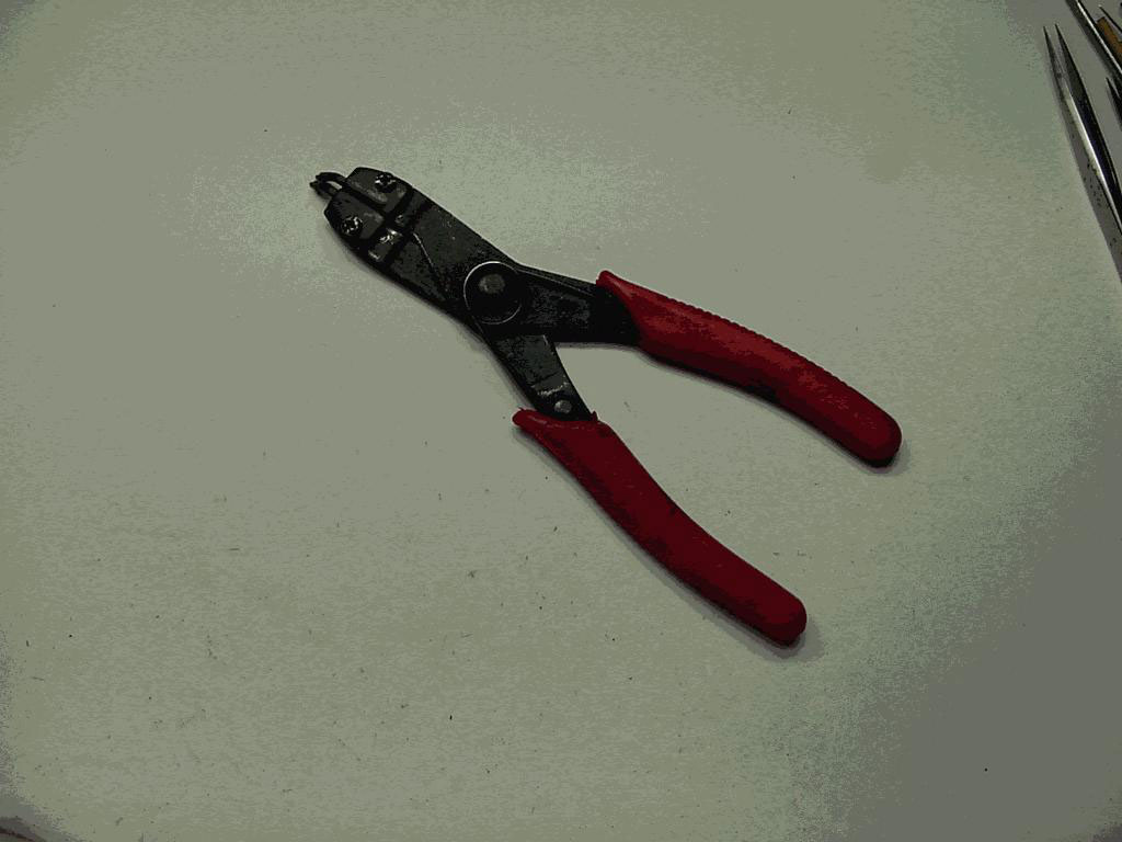
Tools needed.

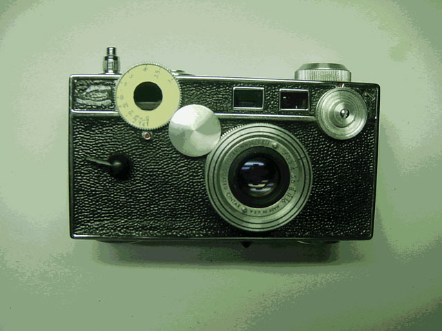
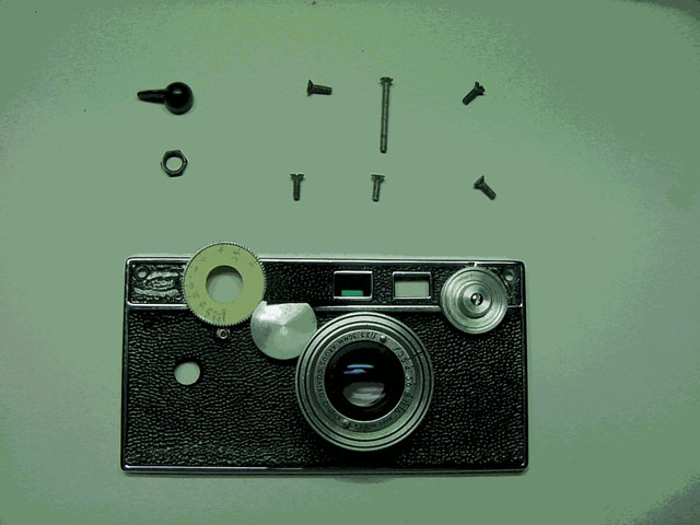
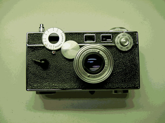
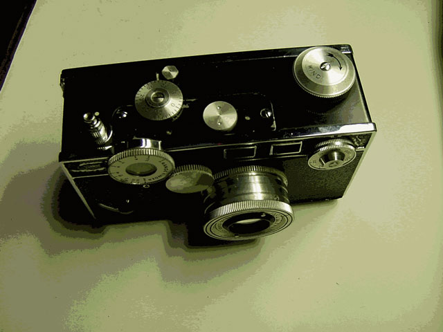
Parts for the C3
Many thanks to Mr. R. Norwood of the ACG for donating the appliqué for the range finder dial and the speed control dial.
Procedure
If shutter is working properly at all speeds and all you need to do is clean the range finder, i.e. you do not need to remove the front of the camera, then all that is needed is to remove the range finder assembly, clean it, oil and grease it, put it back and adjust it.
Removing the range finder without removing the front of the camera.
Open the back of the camera and hold the film winding post while you unscrew and remove the exposure counter dial.
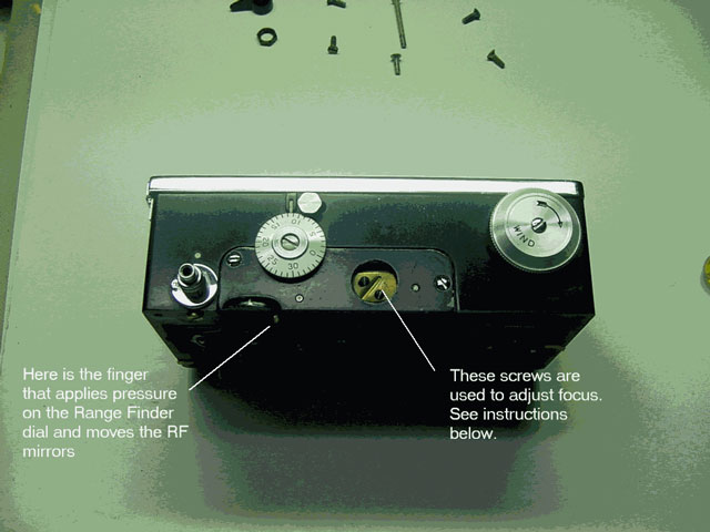
To get that finger out of the way, do the following:
If however you do need to remove the front of the camera to restore the shutter mechanism, then removing the range finder becomes easier and should be done after first removing the front.
TIP 1: To restore the shutter works you do not need to remove neither the taking lens nor the shutter speed dial knob nor the range finder knob. The speed dial knob is screwed to a cam with a knurled shaft that will come apart if the screw is removed.
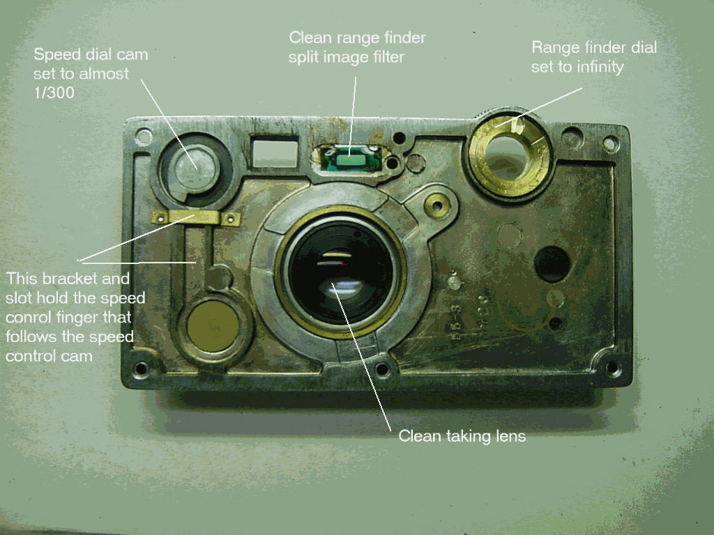
TIP 2: Turn the shutter speed dial to just before the stop at 1/300 sec. This will release spring pressure and yet allow the speed cam follower to move freely.
TIP 3: Turn the range finder dial to infinity to release pressure from range finder finger
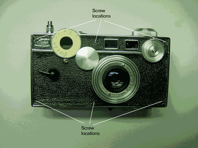
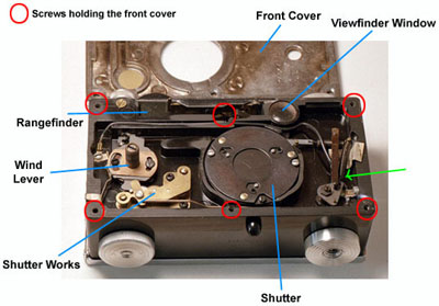
There are six screws holding the front to the bakelite body (shown in red circles). 5 x ½ inch screws (4 at the corners and one at middle bottom) and 1 x 1 inch screw at middle top and about ¼ inch down from the very top edge.
Unless the leatherette is cracked and need to be replaced, then DO NOT REMOVE IT.
Instead, just lift of the leatherette where needed using a flexible and retractable utility knife or a 0.010 inch steel feeler gauge to work under the leatherette and lift it (usually, after so many years, the glue is dry and the leatherette can easily be pried off by gently working the knife under the leatherette while lifting it). Just go far enough to have access to the screw heads (about ½ inch will do). To get access to the screw in the middle bottom, it is safer to lift the leatherette all along the bottom, else it might tear. The leatherette at the top corners will lift completely out of the way. CAREFUL with the leatherette at the middle top as it is held with only 2 thin strips to the rest of it.
WORK GENTLY AND CAREFULLY.
Using a 3/16 inch straight screw driver, unscrew and remove the screws using the tweezers to hold them.
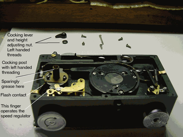
Some C3s have a setscrew to fix the shutter wind lever to its shaft; some have a left-handed thread with a nut for adjusting the height of the lever. So either remove the setscrew and then the lever, or turn the lever clockwise to unscrew it (you will need a small wrench to hold the nut), then turn the nut clockwise to remove it.
Now, with the front of the camera facing up on your bench and the range finder at the top, gently lift the left hand side of the front till the shutter cock shaft is clear (about 3/8 inch), then lift the right side about ¼ inch, then slide the front assembly towards the top of the camera about ½ inch to disengage the speed control cam follower (shown by green arrow). You can now lift the front out of the way.
Flip the front assembly so the lens is on the bench. Brush all areas and blow them. Clean the green plastic range finder half lens and the viewfinder glass. Sparingly grease the range finder cam using sticky grease (just a smear will do). Sparingly grease the bracket that guides the speed control finger.
At this point I replaced the shutter speed knob with a new one that has speed appliqué attached. I also glued the distance appliqué to the range finder knob using a little liquid shellac both parts courtesy R. Norwood of ACG.
Also sparingly grease the contact area of the range finder dial cam.
Set the front assembly aside for later attachment.
Now that the front has been removed, it is easy to remove the range finder.
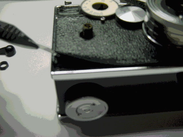
The range finder is held in place by 2 screws. There is also a ½
inch nut with 2 small holes that acts as a cover to access the range finder
adjustments. Unscrew the cover nut using an adjustable spring remover.
Unscrew the 2 assembly holding screws. Lift the range finder assembly using
tweezers.
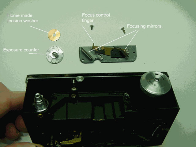
If any mirror is cracked or loose, replace and re-glue with a little liquid shellac. Clean the mirrors using lens cleaner and a clean lint free cloth.
Oil pivots using special oiling needles DO NOT OVER OIL, as oil tends to travel just a tiny drop will suffice.
Using very little sticky grease, smear the end of the finger projecting out of the assembly this makes contact with the range finder dial cam and moves the mirrors accordingly.
Replace the range finder and screw down the 2 screws only do not yet replace the cap as you will need access to the adjustments.
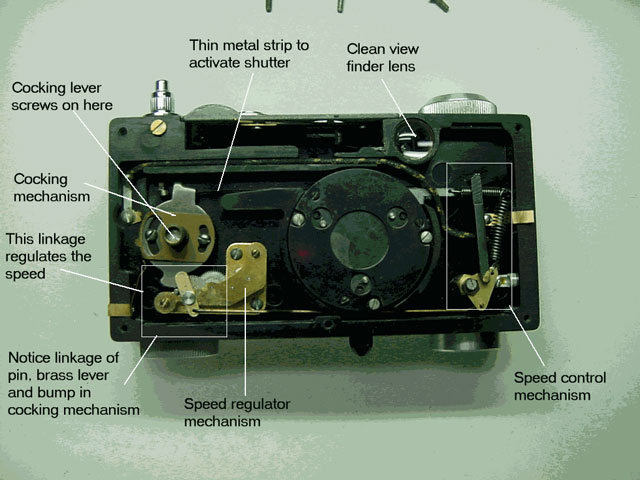
The shutter works consist of several parts: the shutter itself (behind the taking lens); the shutter cocking mechanism (to which the cocking lever is attached); the shutter release regulator (at lower left with the camera on its back and range finder at upper left); and shutter speed control (at lower right).
The whole thing is spring driven and the spring is tightened when the cocking lever is cocked.
Unless the shutter leaves are not operating properly, leave them alone. Just bushing and blowing them should suffice.
If however you see any signs of oil or grease and they need attention then unscrew 3 small screws, remove the large thin holding washer using tweezers or a small amount of rodico. This exposes the leaves. Note the order of the leaves and remove them. Brush them if they are free of oil and grease. If greasy, use a rag with some gasoline to wipe them clean and dry. Now, using a drop of dry carbon dust between thumb and forefinger rub them gently then brush them and blow them to remove all excess dust. Brush and blow the area under the leaves. Replace the leaves in same order they came. DO NOT OIL THE LEAF PIVOTS. Brush the large holding washer, blow it and replace it. Screw down the large washer.
It is a simple spring-loaded cam follower mechanism with a finger that touches a cam on the speed control knob. One spring (small and at the top) operates the shutter, while the other (large and on the side) keeps the linkage to the speed regulator tensioned.
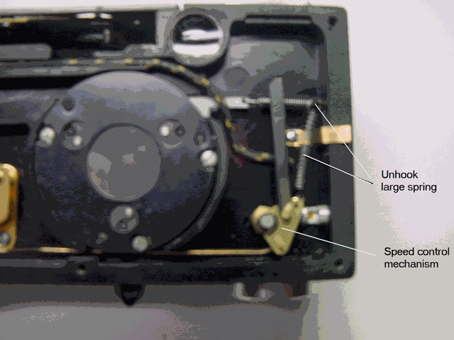
Using tweezers, unhook the large spring from its post.
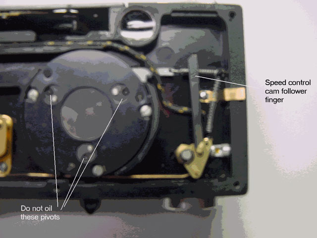
You generally do not need to do much with this mechanism, but a small drop of oil at the only pivot point will help. Wiggle it to make sure it is free and operates easily.
The speed regulator is a geared assembly with a governor that acts to regulate the speed at which the shutter spring is released.
It is held down to the bakelite body with just 2 screws and is linked to the speed control mechanism on the lower right via a stiff wire.
DO NOT REMOVE THE 2 SCREWS AT THE TOP OF THE ASSEMBLY, else the gears will fly off.
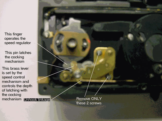
NOTE THE MESHING BETWEEN THE COCKING AND SPEED REGULATOR.
If you look down on the speed regulator mechanism, at the top there is a brass lever (linked with a wire to the speed control mechanism at lower right of body). On the left of this lever there is a spring-loaded pin which activates the lever and thus runs the speed regulator. The brass lever controls the depth of engagement of the pin with the finger on the cocking mechanism. The pin, on the other hand, latches the cocking mechanism finger and is pushed by it when the shutter release button is pressed.
FIRST, RELEASE THE LARGE SPRING OF THE SPEED CONTROL MECHANISM FROM THE POST USING TWEEZERS.
This will relieve tension on the linkage to the speed regulator mechanism.
The speed regulator assembly has some wiggle in its positioning in the body. Make a scratch mark on the body so you can replace it where it was.
Unscrew the speed regulator assembly FROM THE BODY ONLY and unlink it from cocking mechanism and the speed control mechanism.
Soak it ASSEMBLED in a small jar in a little gasoline to cover it. Swish it and brush it 2 or 3 times with a stiff brush and gasoline. This will remove old oil and grease. Test for free operation of the gears and the governor. Repeat cleaning if necessary. Blow it dry when cleaned.
Some people are proponents of leaving the pivots dry. This has some merit if the camera will be operated in very cold weather as the oil will thicken. However, for normal operation I prefer to oil pivots to reduce wear.
Sparingly (a tiny drop) oil all pivots at their pivot holes ONLY.
Sparingly grease the 2 surfaces of the governor (looks like a claw at the rightmost end of the assembly); the hole where the linkage to the speed control is; the steel finger that links to the cocking mechanism; and the contact area of the brass lever between it and the pin.
Set aside for later installation after servicing the cocking mechanism.
The cocking mechanism winds the spring that operates the shutter and has a release mechanism at the top that is released by the shutter release button. It also has a projection at the lower end that meshes with the speed regulator mechanism which controls the speed of return of the cocking mechanism and thus the operation of the shutter.
It needs little attention. If you look down on the shaft you will see a screw head. Unscrew it only a couple of turns, place a couple of oil drops between the screw and inside of the shaft, then screw it down.
Wipe clean all edges of the cocking mechanism and the flash leaf spring.
Make sure the flash contacts are clean, else GENTLY scrape them clean.
Sparingly grease the lower projecting finger that meshes with the speed regulator.
The brass washer edge operates the beryllium copper (springy copper) leaf contact that closes the circuit and provides impulse to the flash. Sparingly grease the left edge of the topmost large brass washer and the flash leaf contact.
There is also a projecting finger on the flash spring that lifts the large brass washer when the cocking mechanism is cocked. This projection needs a little grease.
Replace the large speed control regulator spring on its post.
To test operation at high speed, with the thumb or forefinger cock the mechanism and press shutter release button.
To test operation at low speed, cock the mechanism, fully depress the speed control finger at right hand side, and press shutter release button. You should see the regulator action take effect and the shutter operate at slow speed.
Putting the front back on the camera body takes a bit of dexterity.
Turn distance knob to infinity and speed knob to just before 300.
Hold the body with right hand and the speed control side facing you. Tilt it a little to the left so that the speed control finger is away from the body.
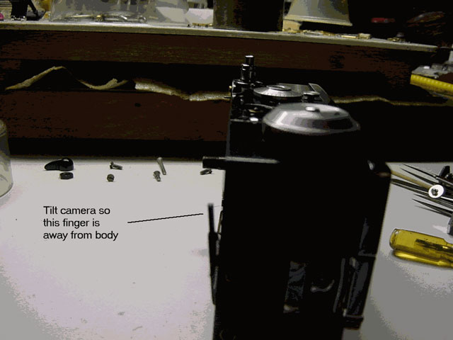
Hold the front with your left hand and first mesh the cocking shaft into its front cover hole then mesh the speed control finger into its guides in the front assembly.
Lay the camera down on the bench, push front towards bottom of camera you should feel a slight pressure between the speed control finger and the speed control cam. Press down at the top you should feel some pressure between the range finder finger and the range finder dial cam. Replace the 4 corner screws.
Turn the speed dial you should feel slight tension as it moves from 1/200 to 1/300 and more tension as it reaches 1/10.
If it feels loose at 1/300, then you need to adjust the position of the speed regulator mechanism, i.e. it needs to be twisted towards the cocking mechanism this will lift the speed control cam following finger towards the cam.
Replace the cocking lever to its correct height and test the camera at all speeds and test the range finder for smooth operation. If all is well replace the last 2 screws and tighten them all.
The C3 range finder has both vertical and horizontal adjustments. Each adjustment is made by twisting one of the screws. The screws are accessible behind the cover nut at the top of the camera. The adjustments are very small.
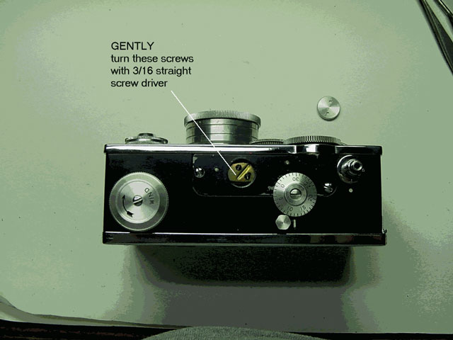
Place the camera on a tripod so you can comfortably see through the range finder.
Place the black cross object at 5 feet. Turn distance dial to 5 feet. View the object through the range finder. Using the 1/8 inch straight screwdriver GENTLY twist one of the adjustment screws and observe the effect on the object. Adjust for horizontal focus first then vertical.

Repeat with the object at 25 feet and range finder set to 25 feet.
Return to 5 feet to check.
If necessary, re-adjust at 5 and 25 feet until you are satisfied dial reads correctly.
Take the camera outside and focus on infinity it should be correct.
When complete, replace the cover nut. DO NOT OVER TIGHTEN.
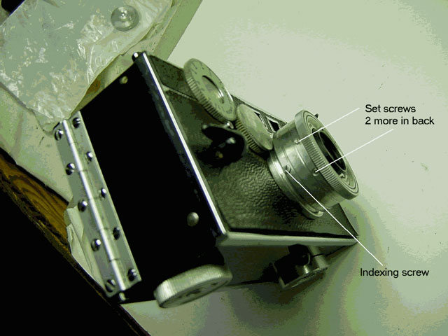
The taking lens has 4 setscrews and a large indexing screw.
Turn the range finder dial to infinity and note the height of the taking lens from the front of the camera and the position of the index hole.
You do not need to unscrew the setscrews or remove them. Unscrew and remove the indexing screw. Now the taking lens barrel can be freely rotated without moving the range finder.
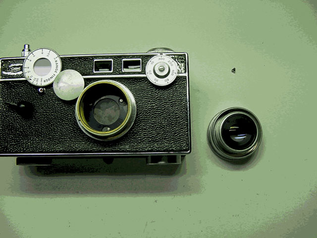
Slowly turn the lens anticlockwise while lifting it up and counting the number of turns of the index hole until the lens just disengages from its threads (about 2 ½ turns). Note where the index hole is when the lens disengages from its threads. Make a mark there with a grease pencil you will need that position to correctly re-engage the lens.
There is a small round lens fitted in the back of the taking lens. To disassemble the lens, so you can clean all faces, use the spring loaded wrench to remove the nut holding this small lens.
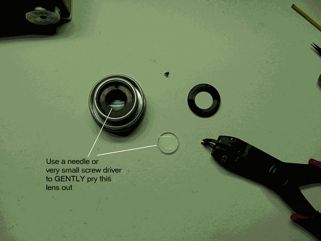
Now you can clean all lens faces. Replace the lens and tighten with the wrench.
Replace the lens starting with the index hole at the mark and screw it down to the correct number of turns and till the index hole matches with its screw hole and the height of the lens from the body is correct.
Replace the index screw and tighten the setscrews.
Clean the grease mark.
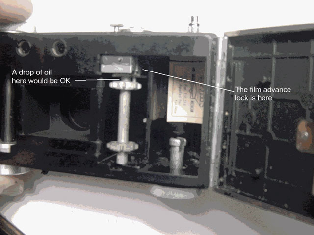
There is little that needs attention inside the body except the taking-up spool.
A drop of oil at its top pivot and sparingly greasing the film stop/lock should do it.
You can use Pliobond or a little liquid shellac to re-attach the leatherette to the body. I prefer the shellac as it does no harm and can easily be lifted with a knife.
This is a 50 or 60 years old camera and I like my antiques to show their age and use - dents and scratches included.
This C3 had its original leatherette and its body was in pretty good condition some paint was rubbed off, but that did not matter.
Using a cloth dampened with soapy water, I wiped the whole body clean thats all.
TIP 1: attempting to patch up paint will make it worse. It will never match up and will be visible. So unless you are prepared to strip and re-paint, leave it alone.
TIP 2: unless the leatherette is in bad shape, leave it alone just clean it.
Load up and take some pictures you will be surprised how good they turn out to be.
11. Comments
Please address any comments or suggestions for improving this article to:
degaon@aol.com