|
|
 |
Service Manual
Model C 3 Army CameraInstructions For Adjusting Range Finder
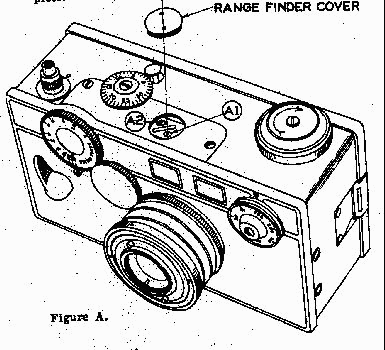
There are only two adjustments to be made in correcting the rangefinder,
when easured distance from the front plate of the camera to target or subject matter does not agree with the reading on the
rangefinder dial scale. Both of these adjustments must be made without removing range-finder assembly or lenses from camera.
Equipment:
(1)
White cardboard target about 2 ft. x 2 ft. with black vertical and horizontal lines about ¼ inch wide and several inches apart
for use at 25 ft distance.
(2) Infinity target to be a vertical object (post, tree, ect.) at about 200 feet or more
from camera.
(3) Wrench for removing rangefinder cap.
(4) Small screw driver.
(5) Tripod or any firm
object on which camera can be firmly placed.
Procedure: (Vertical adjustment)
First make certain that the idler gear or coupler between focus barrel and rangefinder dial wheel is properly set.
Information on this is contained
in the camera instruction book. Rotate range-finder dial wheel to position marked infinitly
on dial scale. Remove (with special wrench) the rangefinder cap which covers the adjustment screws "A1" and "A2" in diagram.
Sight infinity target through rangefinder window. If vertical line appears broken, place tip of screw-driver
against edge
of screw head "A2" and carefully slide forward or backward in slot, at same time noting how the upper half of vertical line
is moved. Moving screw toward front of camera, moves image (or vertical line) to the left. In the opposite direction, the
vertical line is moved to the right. Adjustment on infinity setting is complete when vertical line appears as one line (unbroken).
(Horizontal
Adjustment)
Place camera on tripod. Set rangefinder dial at 25 feet, and place target with horizontal line at 25 feet
from front of camera. Sight target through rangefinder window. If a horizontal line appears as two lines, the adjustment is
easily made by tightening one or the other of the two
screws marked "A1" and "A2" in diagram.
Tightening "A1" raises
image on target. Tightening "A2" lowers the image. When a horizontal line appears as one line, the adjustment is complete.
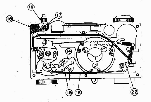
To
Remove Camera Front Plate
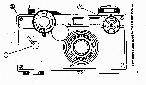
Procedure:
(1) Loosen set screw in cocking lever (1), then
unscrew cocking lever from shaft.
(2) Set shutter speed button (2) to 1/300 to re-lieve tension on cam follower.
(3) Raise
covering over front plate screws (3) at four corners, and cut covering where other two screws are located.
(4) Remove
the six-inch screws. Carefully lift front plate about ¼ inch from bakelite case and then slide front plate in direction of
top of camera. This will prevent bending pin in cam follower.
To replace Shutter
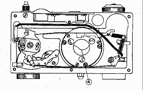 Procedure:
To replace shutter, remove the three mounting screws
(4) from shutter plate and install new shutter in same position. It may be necessary to loosen screws (4) just enough to slightly
shift the position of the shutter assembly toward or away from the shuttle cock catch (12), see figure "D". If shutter blade
arm is too close to shuttle cock, the blades will open too far and sometimes stick in shutter blade housing. If shutter blade
arm is too far from shuttle cock, the shutter will not open fully. Tighten screws when shutter
is positioned.
To
Replace Shuttle Cock Assembly
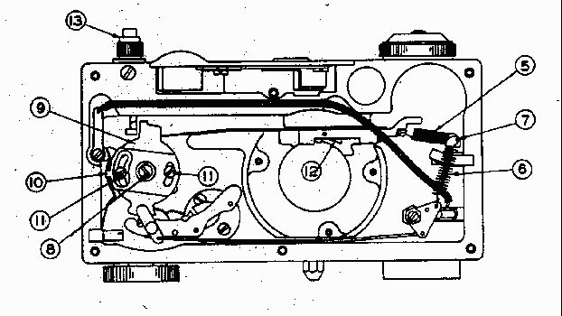 Procedure:
(1) Remove shutter as described in figure
"C".
(2) Unhook springs (5 & 6) from post (7).
(3) Take out screw (8) and remove shuttle cock assembly.
(4) Transfer
shutter release cam (9), switch release arm (10) and two screws (11) from old assembly to approximately the same position
on the new assembly
(5) Set shutter release to "I" position on dial (13)
(6) Install shutter cocking lever (1)
Figure "B" to check movement of shuttle cock and shutter before installing front
plate. Cock shutter by depressing cocking
lever. While holding cocking lever down, press shutter release (13) and gradually
release pressure on cocking lever. Watch
shutter blades open slowly. Shutter must open fully but not so far that the blades
will bind in housing.
To
Replace Shutter Escapement And
Shutter Release Assembly
 Procedure: Shutter Escapement
(1) Before attempting to remove
shutter escape-ment, mark bakelike case around shutter escapement base (14). This will
simplify installing new shutter
escapement in identical position of the original one. Then remove Two screws (15) that hold
escapement assembly to camera
case.
(2) Unhook wire link (16) from control arm of the escapement
Procedure: Shutter Release Assembly
Remove
front plate (see inst. on front plate figure "B"). Remove screw (17). Remove screw (18) and spring beneath screw which presses
against small ball bearing. Carefully pull release assembly (19) from case. Watch for ball bearing which may drop out
when release assembly is removed.
Installing Front Plate
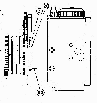 Procedure:
Set shutter speed dial (2) to 1/300 (see figure "B").
Turn front plate over and insert cam follower (20) in bracket (21) with pin pointing away from front plate. Carefully turn
front plate over so as not to disturb position of cam follower. By holding plate at corners with thumb and forefinger of each
hand, lower plate to about ¼ inch above case. Note position of pin in cam follower and hole in triangle lever (22) Fig. "E"
into which pin should be inserted. This allows enough space between camera and front plate so that the pin (23) can be directed
to engage the hole of the triangle lever (22) as front plate is lowered to correct position for inserting screws (3) see Fig.
"B".
To Replace Gear Block Assembly
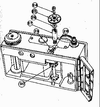 Procedure:
(1) Remove counter dial screw
(24), dial (25), cupped friction washer (26) and post (27). (Insert screw-driver between back gear and case to
prevent parts from turning while removing dial screw.)
(2) Remove screw (28) and unscrew button (29).
(3)
Gear block assembly (30) can then be withdrawn from case cavity.
|
|
|
|
|
|
|
|